Small office: design around the work
An assumed one-floor 12 × 9 m office for 6 fixed wired desks and 6 laptop users, with a 6-seat meeting room. The plan, cable routes and four systems are explained together so readers can understand each placement.
This hypothetical scenario supports a design discussion. It is not a construction drawing, measured result or project quotation.
Design inputs
- This is an illustrative pre-survey design, not a real project, construction drawing or acceptance result.
- The floor is 12 × 9 m with an assumed accessible 3 m ceiling. The origin is the southwest corner; X points east, Y north and Z upward from the floor.
- The IT room is at X=0–3 m, Y=6–9 m; the meeting room is at X=8–12 m, Y=5–9 m. Door crossings and ceiling paths require confirmation.
- 12 staff comprise 6 wired-desk users and 6 Wi-Fi laptop users. Meeting seats do not add staff. AP01 is primary; AP02 is a trial point, not an installed item.
- MDF means the central equipment and cabling rack in the IT room. This one-floor example has no IDF. Equipment roles are specified before a brand or model.
- Hatching marks Wi-Fi areas to test, not measured coverage or signal values. AC supply, door DC power, reader bus and Internet-provider cable lengths are not yet counted.
- The assumed 0.9 m entrance opening is X = 1.3–2.2 m, centred at X = 1.75 m. The reader and controller are at the left frame, X = 1.2 m; the inside REX is at (1.2, 0.37, 1.2) m. Equipment sits clear of the door opening.
- Illustrative door access: one door has an outside reader, inside REX, controller, electromagnetic lock and separate controller/lock DC supplies; no door-state sensor is included. Local DC/control lengths require a survey and are counted separately from network quantities. The closed leaf supports mechanical comparison, not egress simulation.

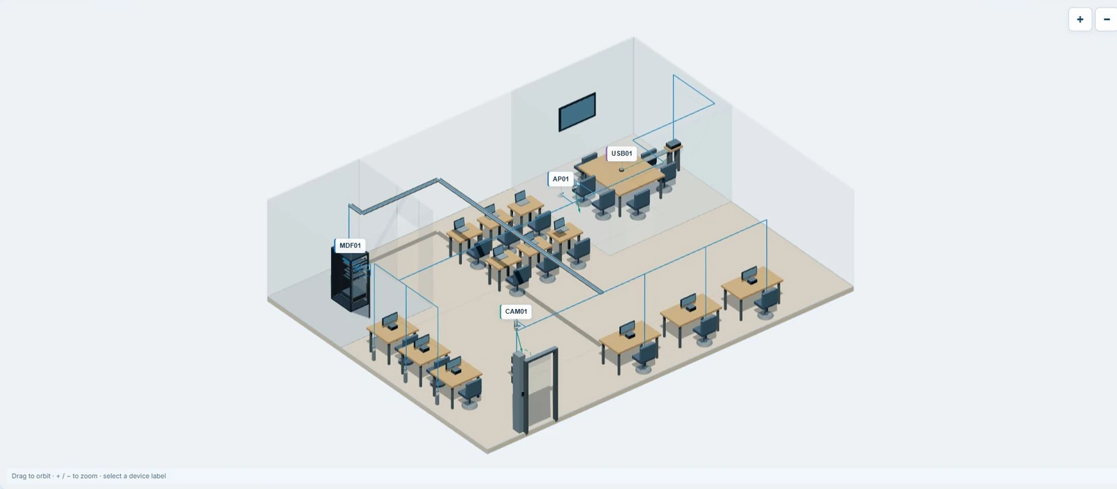
Building the 3D model…
- Cat6 / LAN & PoE
- OS2 fiber
- 100 V speakers
- USB or door control signals
- Lock / controller DC power
- Dashed: control relationship, not a wiring route
Drag to orbit · Scroll to zoom · Arrow keys to rotate · Home for overview
Geometry, placement and connection assumptions
- Coordinates are metres with Z up. Rooms and the 11 Cat 6 routes retain the office-small reference datums. AP02 is a trial point, not installed equipment.
- A 27U 0.6 × 0.8 × 1.6 m outer cabinet is a modelling assumption, front toward −Y. The IT room retains 0.9 m front and 0.6 m rear access; check actual conditions.
- Rack faces use 482.6 mm width and 1U = 44.45 mm. Connection points are route datums, not selected-SKU connector dimensions.
- AV01 is supported on a side console with a cable-management bridge to the meeting table. USB stays local; no new LAN outlet or permanent link is added. Near-device jacks and patch cords are separated in 3D to reconcile the 24 cord schedule; geometry does not represent service slack.
- The 0.9 m entrance opening is x = 1.3–2.2 m. The outside reader and inside exit button are at the left frame, x = 1.2 m. This revised assumption keeps equipment out of the walkway without changing Cat 6 quantities.
- Cameras aim at the entry and circulation as shown on the plan. No face-identification or coverage result is asserted; lenses and lighting remain unselected.
- Cameras use an illustrative custom rigid 200 mm ceiling drop: an anchoring flange at the 3.0 m ceiling connects to the upper camera mounting plane at 2.8 m. This assumed support is not a manufacturer accessory or selected SKU. Loads, anchors, cable protection and construction details have not been engineered or surveyed. Existing body coordinates, connection datums and cable routes are retained.
- The small office has no 100 V PA. USB01 is a table speakerphone, not a wall loudspeaker or horn.
- RELAY-CONTROL depicts only the contact-control relationship between the controller and separately powered lock circuit. The controlReference endpoint is a functional reference, not a physical terminal. This reference is excluded from the equipment schedule and cable quantities; actual wiring, supply, contact ratings and fault behaviour follow the selected equipment and project records.
- ACS01 uses data-only LAN; PSUACS01 supplies controller DC and PSULOCK01 supplies the lock circuit, outside the PoE budget. READER01 faces the entry approach; EXIT01 is inside for an ordinary exit request, not emergency power release. Reader/REX/DC/relay datums identify functions, not a device terminal diagram. This small-office example has no door-state sensor.
- The electromagnetic lock and leaf armature are illustrative, assuming a suitably supported leaf/frame. The device model, voltage, current, lock state on power loss and egress circuit are unselected.
- Door leaves are shown closed to compare lock/armature mechanics, not to simulate operation or egress.
- The MDF has a 24-position patch panel: 11 terminated runs and 13 unused positions. Optional AP02 requires one position and site validation before installation. The 16-RJ45 switch uses 13 ports, or 14 with AP02. SFP cages have no installed optical modules in this example.
- Cable-line colors identify functions rather than actual jacket colors. Provisional lengths require a survey and are not measured from the 3D paths. This example has no installed optical link.
Reference documents:
- Axis: Quality with a purpose
- Axis: Camera positioning
- Schneider Electric: How to Choose an IT Rack
- TOA: Ceiling speaker reference
- Jabra: Table USB speakerphone form reference
- Crestron: Integrated USB audio-bar architecture reference
- Ubiquiti: Ceiling AP mounting reference
- Hikvision DS-K1107AM — Credential reader · Datasheet
- Hikvision DS-K1107AM — Credential reader · Manufacturer guide
- Altronix AL125X220 — Access-control supply · Datasheet
- Altronix AL125X220 — Access-control supply · Manufacturer guide
- Hikvision DS-K2600 Series / DS-K2601 — Door controller · Datasheet
- Hikvision DS-K4H258S — Magnetic lock and armature · Datasheet
- Hikvision DS-K4H258S — Magnetic lock and armature · Manufacturer guide
- Hikvision DS-K7P02 — Request-to-exit button · Datasheet
- Leviton 69586-L24: 24-position panel construction
- Omada TL-SG2218P: 16-RJ45 switch construction
Equipment & proposed cable routes
| ID | Role | Qty | Location | Cable / connection | Proposed route | Conditions |
|---|---|---|---|---|---|---|
| D01 | Wired desk outlet | 1 | West desk 01 | Fixed solid-copper Cat6; patch cords counted separately | 15.55 m | Allow 19.4 m of fixed cable, including 2 m slack and 10% reserve, rounded per run. |
| D02 | Wired desk outlet | 1 | West desk 02 | Fixed solid-copper Cat6; patch cords counted separately | 14.25 m | Allow 17.9 m of fixed cable, including 2 m slack and 10% reserve, rounded per run. |
| D03 | Wired desk outlet | 1 | West desk 03 | Fixed solid-copper Cat6; patch cords counted separately | 14.95 m | Allow 18.7 m of fixed cable, including 2 m slack and 10% reserve, rounded per run. |
| D04 | Wired desk outlet | 1 | South desk 04 | Fixed solid-copper Cat6; patch cords counted separately | 15.35 m | Allow 19.1 m of fixed cable, including 2 m slack and 10% reserve, rounded per run. |
| D05 | Wired desk outlet | 1 | South desk 05 | Fixed solid-copper Cat6; patch cords counted separately | 17.35 m | Allow 21.3 m of fixed cable, including 2 m slack and 10% reserve, rounded per run. |
| D06 | Wired desk outlet | 1 | South desk 06 | Fixed solid-copper Cat6; patch cords counted separately | 19.35 m | Allow 23.5 m of fixed cable, including 2 m slack and 10% reserve, rounded per run. |
| AP01 | Wi-Fi access point | 1 | Open-office ceiling | Fixed solid-copper Cat6; patch cords counted separately | 10.1 m | Allow 13.4 m of fixed cable, including 2 m slack and 10% reserve, rounded per run. |
| CAM01 | PoE camera | 1 | Entrance | Fixed solid-copper Cat6; patch cords counted separately | 14.4 m | Allow 18.1 m of fixed cable, including 2 m slack and 10% reserve, rounded per run. |
| CAM02 | PoE camera | 1 | Common area | Fixed solid-copper Cat6; patch cords counted separately | 11.3 m | Allow 14.7 m of fixed cable, including 2 m slack and 10% reserve, rounded per run. |
| ACS01 | Door-controller LAN | 1 | Near the entrance | Fixed solid-copper Cat6; patch cords counted separately | 15.6 m | Allow 19.4 m of fixed cable, including 2 m slack and 10% reserve, rounded per run. |
| AV01 | Meeting-host LAN | 1 | Meeting room, call host | Fixed solid-copper Cat6; patch cords counted separately | 20.45 m | Allow 24.7 m of fixed cable, including 2 m slack and 10% reserve, rounded per run. |
| AP02 | Wi-Fi access point | 0 | Meeting-room ceiling, trial position | Fixed solid-copper Cat6; patch cords counted separately | 16.6 m | Not installed; select only after trials. Allow 20.5 m of fixed cable, including 2 m slack and 10% reserve, rounded per run. |
| MDF01 | Central equipment and cabling rack | 1 | MDF rack in the separate IT room | No additional permanent Cat6 run | — | Size ventilation, bonding and working clearance for the actual equipment; no IDF rack. |
| RG01 | Gateway / firewall | 1 | MDF rack in the separate IT room | 1 × 1 m Cat6 patch cord to SW01 | — | Uses 1 switch port; WAN cabling depends on the actual Internet service and is not metre-estimated. |
| SW01 | Managed 16-port RJ45 switch | 1 | MDF rack in the separate IT room | No additional permanent Cat6 run | — | 13 used ports; 14 with AP02, leaving 2 spare. Require at least 4 compatible PoE ports and adequate budget for selected devices. |
| PP01 | 24-position Cat6 patch panel | 1 | MDF rack in the separate IT room | 11 active runs; 12 with AP02 | — | 11 terminated positions and 13 unused; optional AP02 uses position 12. Match panel/run/switch labels; gateway/NVR use local cabinet cords. |
| NVR01 | Network video recorder | 1 | MDF rack in the separate IT room | 1 × 1 m Cat6 patch cord to SW01 | — | Select channels, bitrate and disks for retention; separate power, no assumed RAID or PoE. |
| UPS01 | Backup power for in-rack equipment | 1 | MDF rack in the separate IT room | No additional permanent Cat6 run | — | Size from real load, power factor and required runtime. No runtime promise; assess lock power separately. |
| PSUACS01 | Separate controller DC supply | 1 | Inside the door-control area | Local branch lengths require a survey; interface, conductor size and supply follow the selected equipment. These quantities are separate from Cat6 and the provisional cable allowances. | — | One dedicated controller DC supply, outside the PoE budget; match voltage, load and protection to the equipment. |
| PSULOCK01 | Separate lock power supply | 1 | Near the door, subject to PSU layout | DC cable sized for current / voltage drop; length open | — | Separate from switch PoE; confirm safety and power-loss behaviour with a qualified person. |
| LOCK01 | Illustrative electromagnetic lock + armature | 1 | Entrance door | Power from PSULOCK01; control matched to the door system | — | No selected device model, voltage, current, lock state on power loss or egress circuit. |
| READER01 | Credential reader | 1 | Near the entrance | Matched reader bus; length open | — | No assumed OSDP / Wiegand interface. |
| EXIT01 | Exit button / suitable exit device | 1 | Inside the entrance | I/O per door design; length open | — | Does not replace the building’s exit and safety design. |
| USB01 | USB table speakerphone | 1 | 6-seat meeting table | Provisional 2.5 m local USB cable | 1.8 m | Coordinate route 1.8 m; check connector and device limits. No separate LAN port. |
| PATCH-ACTIVE | Active Cat6 patch cords | 24 | Both ends of 11 runs + 2 local rack links | Total 29.5 m; separate from the 210.2 m fixed cable | — | 11 × 1 m at MDF; endpoints: 6 × 2 m, AP 0.5 m, 2 cameras × 0.5 m, ACS 1 m, AV 2 m; RG and NVR add 2 × 1 m. Optional AP02 adds 2 cords / 1.5 m. |
Quantity and power checks
- Each Cat6 route sums coordinate-based segments, including vertical sections. Fixed-cable allowance = round up to 0.1 m of (route + 2 m slack) × 1.10. Slack is fixed cable, not a separate patch cord.
- 11 active runs: 168.65 m route + 22 m slack + 19.065 m reserve + 0.485 m rounding = 210.2 m fixed Cat6. The longest route, AV01, is 20.45 m with a 24.7 m cable allowance.
- Optional AP02: 16.6 m route + 2 m slack + 1.86 m reserve + 0.04 m rounding = 20.5 m. Fixed cable with AP02 would total 230.7 m.
- Active SW01 ports = 6 desks + AP01 + 2 cameras + ACS01 + AV01 + NVR01 + gateway RG01 = 13. AP02 raises this to 14 / 16, leaving 2 spare. PoE serves 3 active devices, or 4 with AP02.
- Separate Cat6 patch cords: 24 cords totalling 29.5 m; AP02 adds 2 cords / 1.5 m. The gateway and NVR each use a 1 m cord already included in 29.5 m; these are not permanent runs.
- PoE watts remain open until models are selected. Provisional criterion: PSE budget ≥ 1.20 × the sum of maximum port allocations required by the chosen devices / modes. The 20% headroom is a design assumption; still check standards and per-port limits.
- USB01 route: 1.8 m; provisionally allow a compatible 2.5 m cable. Size NVR storage from actual bitrate × retention, channel count and recording mode; no retention period is guaranteed yet.
Network and Wi-Fi: start with seats and tasks
This example assumes 12 people: 6 at fixed wired desks and 6 using laptops over Wi-Fi. The 6 meeting seats are used by the same group, not 6 additional staff. AP01 is the main access point; AP02 is a trial position only if measurements and real calls show that the meeting room needs it.

MDF means the central cabling and network equipment rack, located in a separate IT room. All runs return to this rack; no intermediate IDF is needed in this one-floor example. The switch uses 13 ports: 11 home-runs, 1 local NVR link and 1 gateway link. AP02 would raise this to 14; start with a managed 16-port switch role and enough compatible PoE ports.
Cat6 runs follow assumed ceiling circulation paths and door crossings, then drop to the outlets. Staff and guests need separate access rules. VLANs organise traffic; firewall rules, ACLs and Wi-Fi settings must be applied and tested to check isolation.
Terminations and patch cords: fixed cabling terminates at the rear of the patch panel; front cords connect to the assigned switch ports. Eleven field runs use eleven rack-side patch cords; endpoint cords and the gateway/NVR connections are recorded separately.
Cabling, power and connections
- The 11 permanent runs total 168.65 m including vertical sections. Add 2 m slack per run, 10% reserve, then round each run up to 0.1 m: allow 210.2 m of fixed Cat6.
- AP02 is excluded from installed quantities. If selected after trials, allow 20.5 m of additional fixed cable and 2 patch cords totalling 1.5 m.
- Endpoint and rack patch cords are separate: 24 cords / 29.5 m in active use. Specify solid-copper Cat6 for permanent runs and suitable factory-made patch cords; confirm cable type for the actual environment.
Checks before handover
- Certify each permanent link, wiremap and end labels; retain results against D01–AV01. A short route does not replace testing.
- Trial actual work at all laptop positions and meeting seats; record conditions and results before deciding on AP02.
- Check ports, each device’s PoE compatibility and the total power budget with all devices operating.
- Test Staff / Guest access and camera / access permissions; retain configuration and recovery instructions.
Cameras: trial the required view before selecting equipment
CAM01 watches the entrance; CAM02 faces the common area. These positions support reviewing events at the door and circulation space, not an assumed face-identification result or complete office coverage. Keep private areas and the IT room out of view, and trial the actual frame before mounting.

Both cameras receive data and PoE from SW01. NVR01 is a separate recorder in the MDF, with a short local LAN patch cord and its own power. Match resolution, bitrate, frame rate, channel count and desired retention to the recorder and disks. This principle assumes neither RAID nor built-in NVR PoE.
The image trial should include people walking through the entrance, backlighting and low-light conditions relevant to operating hours. Then check viewing permissions, time synchronisation, playback and export of a sample clip so the manager understands the usable image and storage location.
Cabling, power and connections
- CAM01 route: 14.4 m; fixed-cable allowance: 18.1 m after slack and reserve. CAM02: 11.3 m / 14.7 m allowance. Both are included in the 210.2 m total.
- Allow a 0.5 m endpoint patch cord and a 1 m rack patch cord per camera. The 1 m NVR–switch cord is local, not a third camera home-run.
Checks before handover
- Approve views and private-area exclusions; retain day / low-light samples with test conditions.
- Check connection loss / recovery, time sync, playback and export with the assigned user roles.
- Reconcile storage and retention against actual bitrate; document recording mode and remaining limitations.
Door access: entry permissions and everyday exit
The entrance has READER01 outside for entry authentication, EXIT01 inside for an exit request, and ACS01 for access permissions. PSUACS01 supplies controller DC; PSULOCK01 supplies the lock circuit separately. This small-office example has no door-state sensor.

The reader faces the entry approach and the request-to-exit button is inside. Ordinary REX requests an action from the controller; it is not an emergency power-release device. Egress and integrations need a separate design for the door and building.
The controller uses data-only LAN and a separate DC supply; lock power is a distinct branch. Relay contacts control the lock circuit but do not generate power. The dashed line is a functional relationship, not an extra cable, terminal diagram or finalized wiring circuit.
The electromagnetic lock and leaf armature are illustrative and assume suitable leaf/frame supports. The device model, voltage, current, lock state on power loss and egress circuit require project selection. The closed leaf supports mechanical comparison, not an operational simulation or safety approval.
Cabling, power and connections
- The ACS01 LAN run has a provisional 19.4 m fixed Cat6 allowance; patch cords are counted separately.
- Local branch lengths require a survey; interface, conductor size and supply follow the selected equipment. These quantities are separate from Cat6 and the provisional cable allowances.
- Reader and REX use distinct interface groups; cores, conductors and power follow the equipment. The dashed relay shows function and is not used for cable quantities.
Checks before handover
- Verify device models, supplies, lock load, interfaces and wiring records before installation.
- Test permissions, ordinary REX and release timing; check door closure directly.
- Network loss, power loss, emergency release and egress require an authorized project-specific scenario; this diagram does not establish those conditions.
Meeting room: a dependable connection and usable speech
AV01 is the meeting host, which can be a computer or laptop suited to the company’s application. It has one LAN connection to the MDF. USB01 is a table speakerphone with a local USB connection for audio input and output; these roles do not create two LAN ports.

The coordinate-based USB table route is 1.8 m. This example provisionally allows a 2.5 m cable, but connectors and device limits must be confirmed before purchase. Trial a two-way call from all 6 seats, including normal speech, echo and mute operation. This is neither a vendor-certified meeting room nor a measured acoustic result.
The office example includes no public-address system. A future 100 V PA system needs a separate amplifier, speaker, zone, load and speaker-cable design. Do not connect a 100 V speaker line to LAN, USB or an unsuitable audio input.
Cabling, power and connections
- AV01 LAN route: 20.45 m; allow 24.7 m of fixed Cat6 within the total. The 2 m endpoint and 1 m rack patch cords are separate.
- USB01 does not return to the MDF. Use the provisional 2.5 m USB cable only after confirming compatibility. No PA speaker cable is counted because this example has no PA.
Checks before handover
- Call using the actual application, select the correct microphone / speaker, and test LAN while other devices are active.
- Trial speech and listening from all 6 seats, mute operation and USB reconnection.
- Record table layout, levels and audibility limits; show users how to start and end a meeting.
Technical references
- Fluke Networks — Top 10 Cable Testing Mistakes
Phân biệt permanent link và channel; đo kiểm cáp, không suy chất lượng từ độ dài tuyến. Permanent-link and channel testing are distinct.
- Ubiquiti — PoE Availability and Modes
Đối chiếu chuẩn PoE, từng thiết bị và ngân sách cấp nguồn. Check device modes and total PoE budget.
- Ubiquiti — Implementing Network and Client Isolation
VLAN grouping and isolation enforcement require separate configuration and verification.
- Cisco — What Is a Managed Switch?
Vai trò switch quản lý trong cấu hình và theo dõi mạng. Managed-switch role, not a selected product.
- Axis — Lenses in surveillance
Góc nhìn và chất lượng hình phụ thuộc ống kính, ánh sáng và chuyển động. No measured coverage inferred.
- Security Industry Association — OSDP
OSDP là một lựa chọn giao tiếp đầu đọc / bộ điều khiển, không mặc định cho mẫu chưa chọn thiết bị. Reader/controller interface scope only.
- Microsoft — Meeting room planning guidance
Chọn thiết bị theo phòng, cách sử dụng và kiểm tra âm thanh; mẫu này không tự nhận chứng nhận Teams Rooms. Room and peripheral planning only.
- TOA — ATT-100VI
Đường loa 100 V và tín hiệu line là vai trò khác nhau; không dùng như đường LAN / USB. No PA model is selected.
- Hikvision DS-K1107AM — Credential reader · Datasheet
Reference for reader construction, mounting and the documented interface revision. Do not transfer this reference model’s protocol or terminals to every illustrative device.
- Hikvision DS-K1107AM — Credential reader · Manufacturer guide
Reference for reader construction, mounting and the documented interface revision. Do not transfer this reference model’s protocol or terminals to every illustrative device.
- Altronix AL125X220 — Access-control supply · Datasheet
Reference for the AL125220 family’s DC supply, enclosure and protection roles. No project supply, voltage or battery is selected; this is not a PoE switch.
- Altronix AL125X220 — Access-control supply · Manufacturer guide
Reference for the AL125220 family’s DC supply, enclosure and protection roles. No project supply, voltage or battery is selected; this is not a PoE switch.
- Hikvision DS-K2600 Series / DS-K2601 — Door controller · Datasheet
Reference for distinct LAN, reader, REX, door-contact and lock-control functions. Generic enclosures and 3D interface datums are not a selected DS-K2601 or manufacturer pinout.
- Hikvision DS-K4H258S — Magnetic lock and armature · Datasheet
Reference for the magnetic body, armature and door/frame support. This selects no SKU, holding force, supply, power-loss behaviour or egress design.
- Hikvision DS-K4H258S — Magnetic lock and armature · Manufacturer guide
The guide pairs DS-K4H250/450/258 locks with the named DS-K2800 controller family. Reference for control/power roles only; do not transfer its terminals to DS-K2600 or generic enclosures, or treat it as an egress design.
- Hikvision DS-K7P02 — Request-to-exit button · Datasheet
Reference for an ordinary mechanical REX button and its contact role. It does not select emergency power release or establish an egress design.
- Leviton 69586-L24: 24-position panel construction
Reference 24-position Cat6 panel and front/rear terminations; no project model selected.
- Omada TL-SG2218P: 16-RJ45 switch construction
Reference RJ45/SFP/PoE layout; actual model, supply and power budget require separate selection.